Looking for an affordable, easy-to-build directional antenna for 2 meters (144–148 MHz)? This collapsible Yagi antenna—made primarily from a tape measure—offers excellent performance and portability. Whether you’re tracking down hidden transmitters, operating in the field, or teaching radio fundamentals, this project is a fantastic addition to your ham toolkit.
Materials List
-
1 PVC Tee (3/4”) $1.00 – $2.00
-
2 PVC Cross Fittings (3/4”) $2.00 – $4.00
-
PVC Cement/Adhesive $4.00 – $6.00
-
3/4” Schedule 40 PVC Pipe $2.00 – $3.00
Minimum length: 25 inches
-
6 Hose Clamps $3.00 – $5.00
Sized to securely fit around 3/4” PVC pipe
-
8-Foot RG-58 Coaxial Cable $10.00 – $15.00
With a connector on one end (I soldered a female BNC connector to mine)
-
5-Inch Wire Segment $0.50 – $1.00
We used 18 AWG solid copper wire, though most types should suffice
-
Measuring Tape $7.00 – $10.00
1” wide metal tape (for the antenna elements)
-
Rosin-Core Solder $5.00 – $8.00
💰 Total Estimated Cost: $34.50 – $54.00
Note: Prices are approximate and may vary based on retailer, brand, and current market conditions.
Tools Needed
- Pipe cutters
- Sandpaper
- Scissors or shears
- Screwdriver or wrench (for hose clamps)
- Soldering iron
- SWR meter
- Tape measure
- Wire stripper
Step 1: Cutting and Assembling the PVC Structure

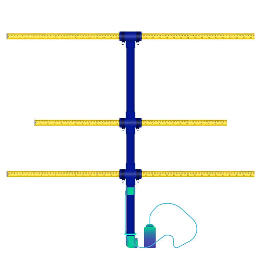
Begin by cutting two sections of 3/4″ PVC pipe—one measuring 17 ½ inches and the other 7 inches. These will form the main support structure of the antenna (the “boom”) along with the PVC fittings.
To assemble the frame:
Connect the 17 ½” pipe between the front-facing tee and the first cross fitting.
Then, insert the 7” pipe between the first and second cross fittings.
Use PVC glue to secure each connection.
Next, pull the metal tape from the measuring tape case until you reach the internal spring. Rotate and detach the tape from the spring mechanism.
Now, cut the following elements from the metal tape:
Director: 35 ⅛”
Driven Elements (2 pieces): 17 ¾” each
Reflector: 41 ⅜”
Be sure to sand all ends of the tape strips smooth to eliminate sharp edges. Also, sand off about ½” of paint from the underside of both driven elements where wires will later be soldered.
💡 Tip: When mounting the antenna to a mast, ensure the active elements sit forward of the mounting point. Mounting at the center of the boom can reduce Yagi antenna performance.
Step 2: Mounting the Antenna Elements
Start at the front of the boom by sliding a hose clamp onto the PVC tee. Position the director element beneath the clamp, then tighten it securely in place.
Next, attach the driven elements to the frame just behind the director. Make sure the sanded sides face each other, with a 1-inch gap between the two pieces. Align them carefully, then fasten them using hose clamps.
Lastly, move to the back of the boom and mount the reflector element using another clamp. Once properly aligned, tighten it firmly to secure the setup.
Step 3: Solder the Feedpoint Connections


Begin by tinning the sanded ends of the driven elements. Heat your soldering iron and apply a small amount of solder to each exposed spot on the tape measure. These pads will serve as soldering points for your wire connections.
Next, prepare the RG-58 coax cable by stripping back the insulation to separate the center conductor from the shielding.
Solder the center conductor to one driven element.
Solder the shield to the opposite element.
Then, strip the 5-inch wire and solder each end to the two driven elements—this forms the other half of the dipole connection.
🔧 Optional: For easier handling or mounting, you can attach an extra piece of PVC pipe with an elbow fitting to the rear of the boom.
You may also choose to leave the PVC joints unglued so the antenna can be disassembled for transport or storage.
Step 4: Tune the Antenna for Best Performance
Tuning your antenna is straightforward. Start by connecting an SWR meter between your radio and the antenna. Set your radio to 146.580 MHz, then check the SWR reading.
If the SWR is higher than 1.2:1, power off your radio and make small adjustments:
Loosen the hose clamps holding the driven elements.
Gently slide the elements closer together.
Re-tighten the clamps, power the radio back on, and check the SWR again.
Repeat the process as needed until you reach an acceptable reading—ideally as close to 1:1 as possible.
⚠️ Important: Always turn off your radio before making adjustments to avoid potential damage.
✅ Note: Some builds may work well without any tuning. In this case, the antenna tested nearly perfect on the first try.
Step 5: Technical Notes and Resources
📈 Performance Insights
According to antenna modeling software, this tape measure Yagi offers approximately 7.3 dBd of gain.
In real-world testing with a handheld transceiver at just 5 watts, we successfully accessed a repeater 65.7 miles away with a clear signal. Other repeaters within 40–50 miles were also easily reached.
Performance may vary depending on terrain, elevation, and local interference.
🔄 Adapting to Other Bands
While this build targets the 2-meter VHF band, it can be easily redesigned for other bands such as 1.25 meters, 70 cm, or 33 cm. To calculate new element lengths and spacing, refer to Yagi-Uda calculators—like the one by Martin Meserve (K7MEM) available here.
📚 Original Design References
Joe Leggio (WB2HOL): Original antenna plans available on his site — WB2HOL Tape Measure Yagi
KC0TKS Website: Additional build variations
NT1K Website: Alternate design and insights

